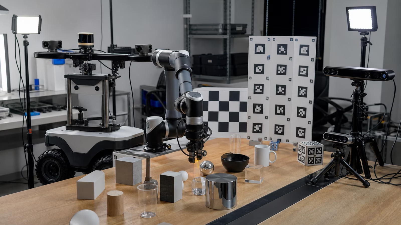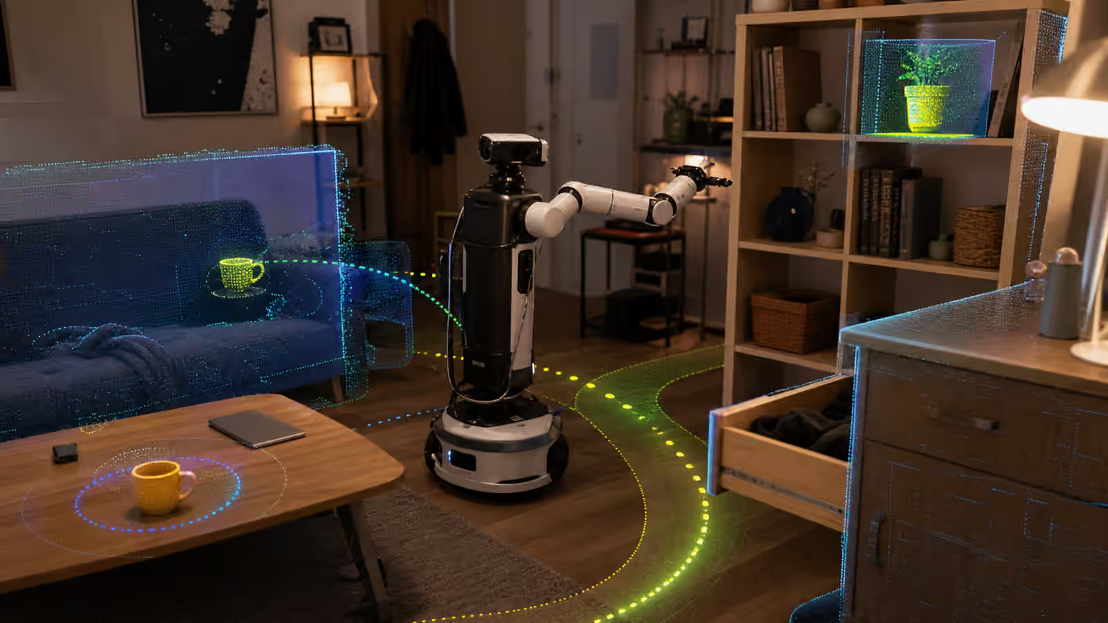
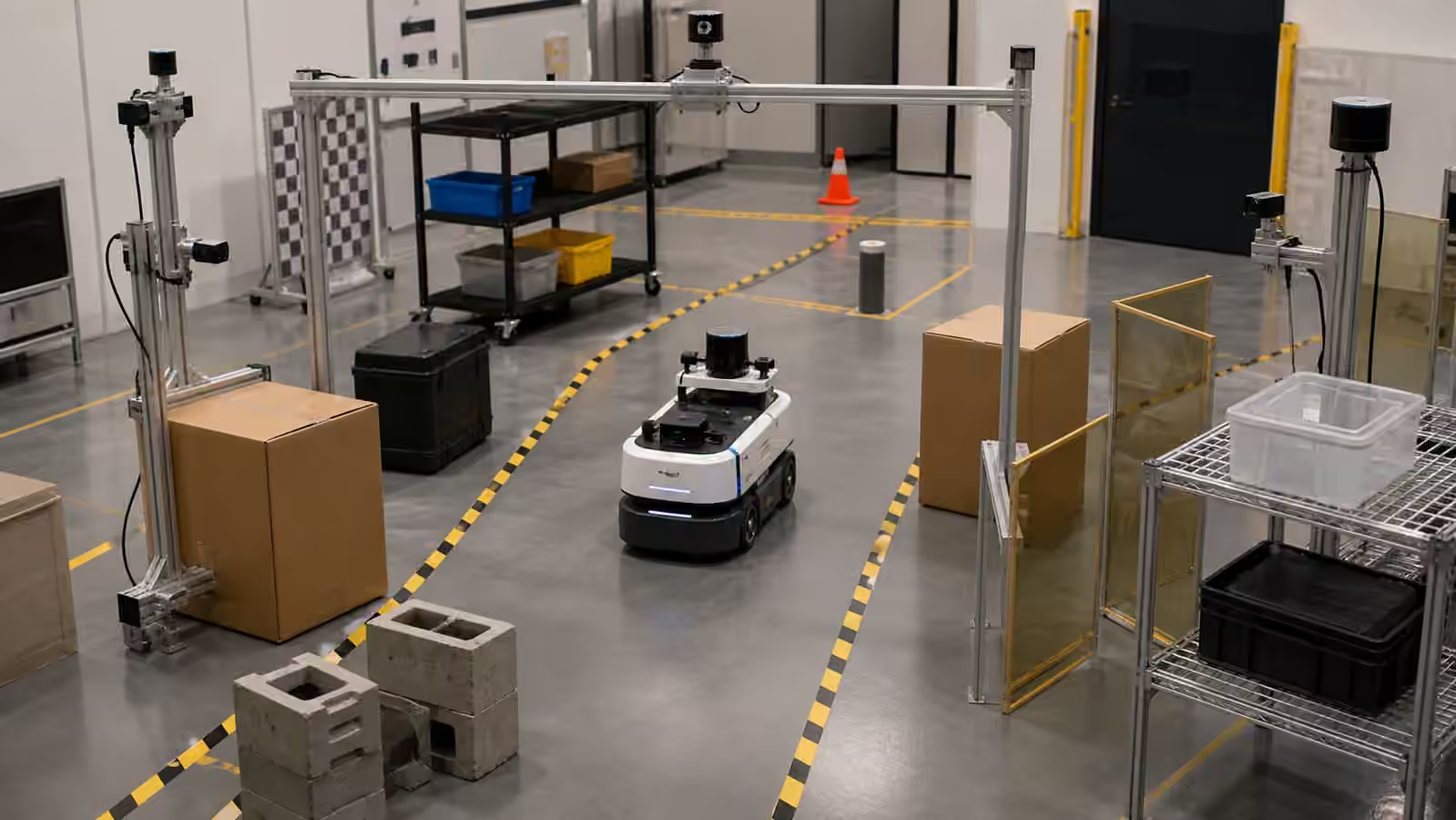
A robot’s world begins where its sensors are mounted.
That sounds obvious until a failure appears in the field. The robot did not see a pallet tine because the camera was too high. It stopped late for a low object because the lidar plane passed over it. It misjudged a shelf because the wrist camera saw the object only after the gripper blocked the view. It lost localization when a decorative glass wall reflected the scene. It avoided a phantom obstacle because dust sat on a cover. The algorithm may receive the blame, but the sensor geometry wrote the first draft of the problem.
Sensor placement is one of the places where physical AI becomes plain engineering. Robot Perception explains how robots turn sensors into scene understanding. Placement decides which scene is available. A better model cannot recover evidence that never reached the camera, lidar, depth sensor, force sensor, encoder, or microphone. The machine’s intelligence is constrained by its viewpoint.
Field Of View Is A Promise With Edges
Every sensor has an advertised field of view, but the useful field is smaller and more conditional. A camera may technically see a wide angle while producing weak detail at the edge. A depth sensor may work well at one distance and struggle closer or farther away. A lidar may scan a clean horizontal plane while missing a hanging strap above it or a low fork below it. A wrist camera may inspect a part beautifully until the final approach turns it away from the object.
The promise of a sensor is therefore not only its datasheet. It is the volume of space where the robot can use that signal for the task. That volume changes with mounting height, tilt, vibration, lens choice, lighting, covers, cable routing, protective frames, and the robot’s own body. A sensor on a mast may see over a tote but become vulnerable to door frames. A sensor behind a protective window may stay safe but gain reflection. A sensor placed for navigation may be badly placed for human interaction cues.
Good placement begins with the task, not the sensor catalog. What must be detected early? What must be classified closely? What must be measured repeatedly? What can be ignored? The answers differ for a mobile robot in an aisle, a robot arm reaching into a tray, a home robot near furniture, and a humanoid walking through doors. Sensor geometry should be judged against the work, not against a generic idea of coverage.
Blind Spots Are Operational Facts
Blind spots are not always defects. Some are unavoidable. A mobile base cannot see directly through itself. A robot arm can hide the object it is reaching for. A payload can block side sensors. A door frame can hide a person until the robot turns. A high shelf can cast a visual shadow over items below it. The problem is not that blind spots exist. The problem is pretending they do not matter.
A deployment-ready robot should know how its blind spots affect behavior. It may slow before turns because the view opens late. It may require a staging zone to keep people out of a hidden approach path. It may ask for confirmation before reaching into an occluded bin. It may rely on bumper, force, or proximity sensing as a last layer but should not treat contact as ordinary perception. Robot Contact Sensing and Force Control is useful here because touch can help the robot respond carefully, but it should not become an excuse for careless seeing.
Blind spot review should include ordinary site objects. A pallet jack, a cable, a garment, a clear plastic bin, a black mat, a chair leg, a reflective appliance, and a hanging sign can all expose different limits. The review should also include the robot’s own states. A robot carrying a tote sees a different world from the same robot empty. A robot with a tool attached has different occlusions from a robot with a bare wrist. A robot near a dock may be partly blinded by the dock it needs to use.
Mounting Is Mechanical Design
Sensor mounts are sometimes treated as afterthought brackets. In robotics, they are perception hardware. A mount that vibrates changes the signal. A mount that bends after a bump changes calibration. A mount that is hard to clean changes field reliability. A mount that exposes a lens to dust, water, or impact changes uptime. A mount that blocks maintenance access creates service friction.
The mount also decides whether calibration remains true. A camera and lidar pair may be calibrated carefully in the lab, but a small shift after shipping, cleaning, or collision can make the fused scene unreliable. Robot Calibration and Alignment explains why geometry is not a one-time ritual. Placement should make calibration checkable. If a sensor can move, the system should have a way to notice. If a cover can be removed, it should return to the same position. If a mast can flex, the design should account for motion.
Mechanical protection needs judgment. A strong cage may protect a sensor from impacts but block part of the view. A recessed lens may stay safer but collect grime. A flush cover may clean easily but reflect lights. A high mast may improve visibility but hit low obstacles. The right answer depends on the environment and the consequence of missing evidence.
Lighting And Materials Change The View
Placement is not only about where the sensor sits. It is also about what light and material reach it. A camera facing a window may work in the morning and fail in the afternoon. A depth sensor may struggle with shiny steel, black rubber, transparent packaging, or fine mesh. A lidar may behave differently near glass, mirrors, rain, dust, or dark absorbent surfaces. A thermal sensor, microphone, or tactile array has its own environmental limits.
Robot Environmental Robustness gives the broader testing frame. Sensor placement should be reviewed across the realistic range of lighting, dirt, temperature, vibration, and surface conditions. A robot that sees a clean lab beautifully may not see a dusty loading dock, a sunlit lobby, a kitchen with reflective counters, or a warehouse aisle after a shift change.
One practical habit is to test against contrast, glare, and clutter before the pilot becomes public. Move the object toward the edge of the view. Put a bright background behind it. Put a dark item on a dark surface. Add the packaging that people actually use. Let the robot approach with the payload it will carry. Many perception surprises become visible when the team stops testing the center of the frame.
Redundancy Needs A Reason
Adding more sensors can help, but redundancy is not simply quantity. Two sensors with the same blind spot do not create resilience. A camera and a depth sensor mounted together may both fail when a payload blocks them. Multiple cameras can create more evidence and more calibration burden. A lidar, camera, encoder, inertial unit, and contact sensor can support each other only if the system knows how to weigh disagreement.
Robot Sensor Fusion and Uncertainty is the natural companion to placement. Fusion should know when one sensor is likely wrong because of geometry, environment, or state. A low obstacle may be trusted more from a near-field sensor than a high camera. A reflective surface may reduce confidence in depth. A wheel encoder may drift on a slippery floor. A camera may lose useful evidence during glare. Fusion is strongest when placement and uncertainty are designed together.
Redundancy should also match safety. A robot that depends on seeing people in a shared aisle may need different sensing from a robot inside a fenced cell. A robot that reaches near fragile objects may need force and tactile feedback even if vision is excellent. A robot that navigates ramps may need sensing that captures ground changes, not only obstacles at one height. The useful question is not “How many sensors does it have?” It is “Which failure is each sensor reducing?”
Maintenance Changes Perception
Sensors age and get dirty. Lenses scratch. Covers cloud. Mounts loosen. Cables strain. Fans pull dust across optics. Cleaning crews wipe surfaces with the wrong material. A robot that began with good visibility can lose it slowly enough that no one notices until exceptions rise.
This is why sensor placement belongs near Robot Maintenance and Reliability . A lens that cannot be inspected quickly is a reliability problem. A cover that needs frequent cleaning should be reachable without disassembling the robot. A sensor health alert should distinguish between temporary obstruction, likely contamination, and deeper hardware fault. The field team should know what a dirty sensor looks like in logs and behavior.
Maintenance planning should include calibration after service. Replacing a sensor cover, adjusting a bracket, changing a mast, or repairing a bumper can change the robot’s view. If the support process treats the sensor as a replaceable part but ignores geometry, the robot may return from service with a subtle perception error.
Sensor Placement Shapes The Site
Sometimes the answer is not moving the sensor. It is changing the site. A mirror can be covered. A route can avoid a blind corner. A staging point can keep objects inside a reliable view. A dock can be moved away from glare. A shelf can be modified so the robot sees the item before it reaches. A floor marking can help people avoid standing where the robot has poor coverage.
Robot Site Readiness and Robot Shared Space Traffic both matter because perception is a relationship between robot and place. A robot does not see in a vacuum. It sees a building with habits. The building can make the sensor layout sensible or cruel.
The most honest sensor review asks people to walk the route and stand where trouble is likely. Where does the robot first see a person? Where does it lose sight of the payload? Where does the camera face a bright door? Where does a worker naturally place a cart? Where does the robot’s own body hide the tool? These questions turn blind spots from abstract diagrams into deployment decisions.
Seeing Is Designed Before Understanding
Robotics teams often want to talk about recognition, planning, and reasoning. Those layers matter, but they sit on top of sight lines, mounts, covers, light, dirt, vibration, and clearance. A robot that cannot get useful evidence will produce uncertain behavior no matter how elegant the software looks.
Good sensor placement does not remove all ambiguity. It makes ambiguity visible and bounded. It lets the robot know where it can trust its view, where it should slow down, where it should ask for help, and where the site should change. In physical AI, seeing is not just a model output. It is a designed condition of the work.