The PCB is the part of a mechanical keyboard most people understand last, even though it quietly decides many of the choices that feel like they belong somewhere else. It decides which layout positions exist, which stabilizers fit, whether switches can be swapped without soldering, how the USB connector is handled, where the LEDs sit, and how much freedom the firmware can expose. The case and keycaps make the keyboard visible. The switches make it tactile. The PCB is the map underneath everything.
For a first build, it is tempting to treat the PCB as a simple checklist item: hot-swap, QMK, correct layout, done. That is often enough, but only if you know what those words imply. A hot-swap board can still block the layout you wanted. A solder PCB can be friendlier than expected if it supports many bottom-row choices. A board with attractive lighting can create keycap interference if its LEDs face the wrong direction for the caps you plan to use. None of these details are mysterious once you know what to look for, and they are much easier to consider before the board is assembled.
If you are still choosing the larger parts of a build, read Building Your First Custom Keyboard first. If you already know you want to solder, the Keyboard Soldering Guide explains the hand skills. This guide sits between those two: it explains what the PCB itself is asking from the rest of the keyboard.
What the PCB actually does
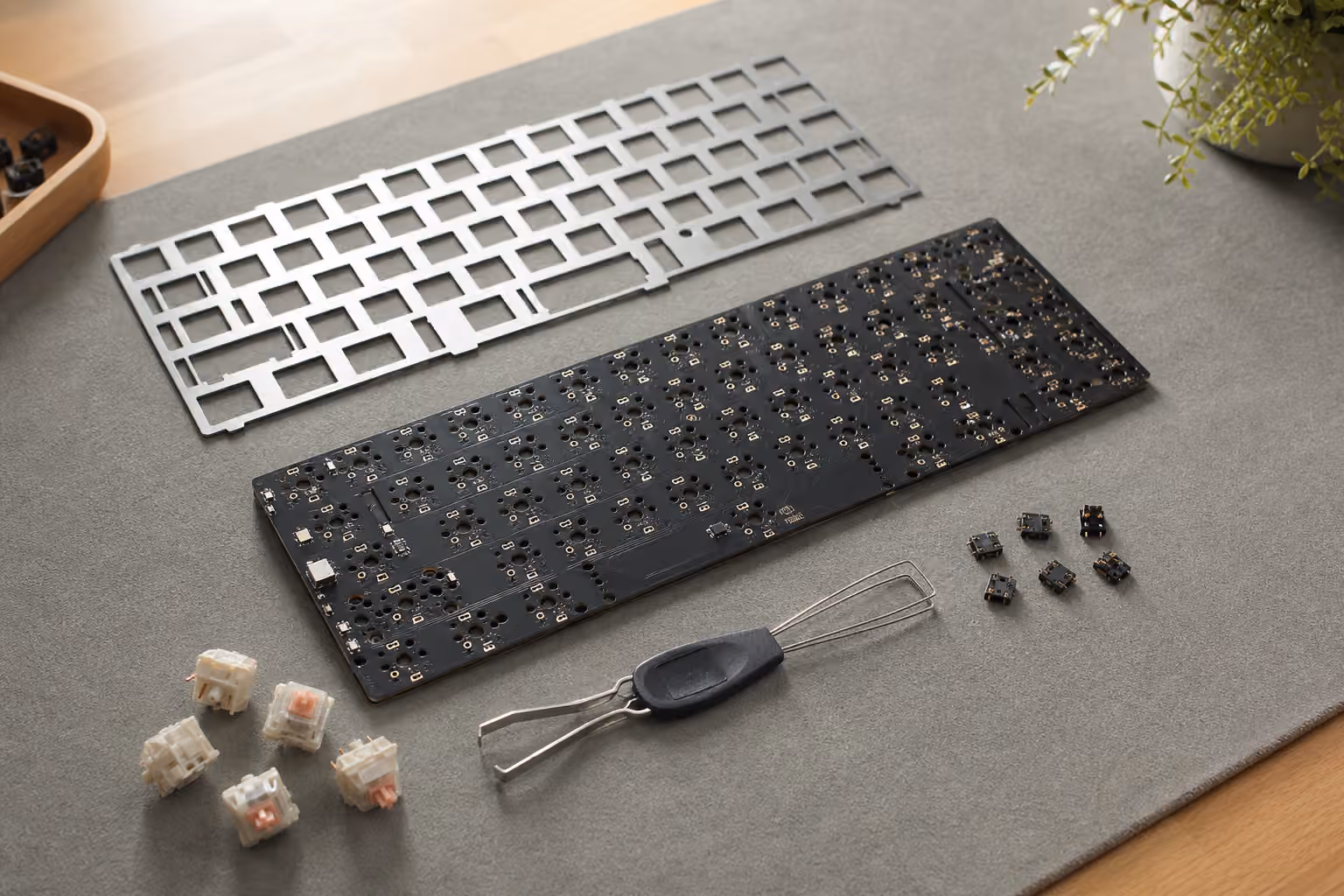
A keyboard PCB is a printed circuit board with switch positions, electrical traces, a controller, diodes, USB hardware, and often lighting circuits. When you press a key, the switch closes a circuit at one position in the keyboard matrix. The controller reads that change, translates it through firmware, and sends the result to the computer. That sounds abstract, but it becomes practical the moment you choose parts.
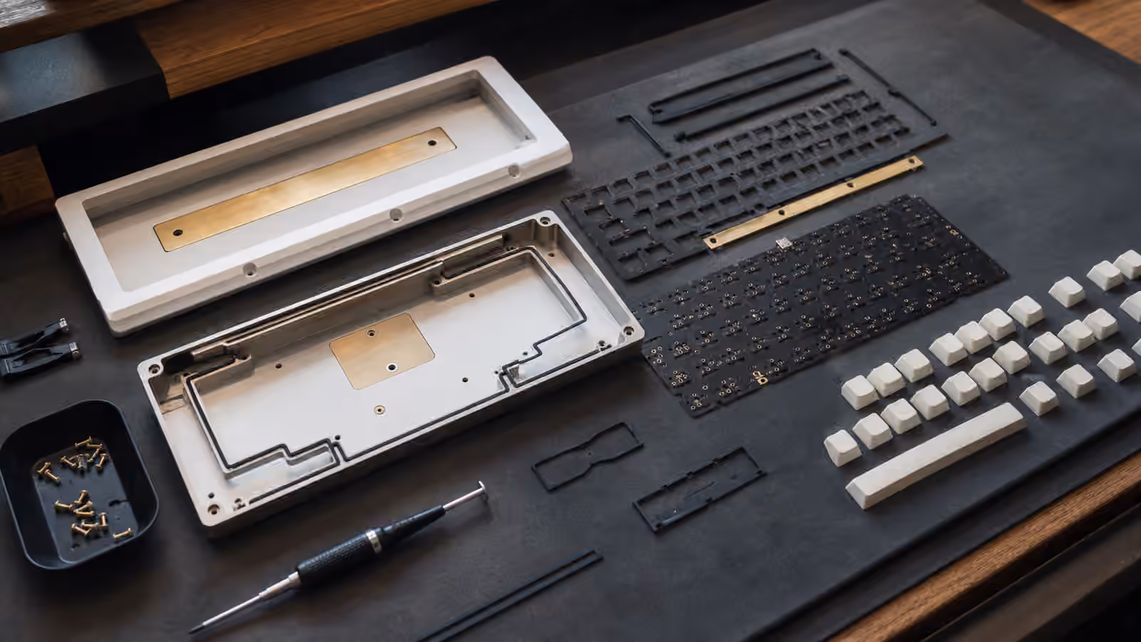
Every switch position on the PCB is a physical promise. If there is no support for split Backspace, you cannot add it by wishing. If the PCB supports ISO Enter but the plate does not, the build still will not work in ISO. If the PCB has both stepped and full Caps Lock positions, you need a plate and keycap set that agree. The keyboard only comes together when the PCB, plate, stabilizers, switches, keycaps, case, and firmware all describe the same layout.
This is why a barebones kit can be easier than a from-scratch parts list. In a kit, the maker has already matched the PCB and plate to the case. When you buy parts separately, you become the person responsible for that compatibility. That does not mean you need to memorize every footprint. It means you should slow down when a product page says things like multi-layout, ANSI only, ISO support, split right Shift, 7u bottom row, or solder only. Those are not decorative specifications. They are the shape of the finished keyboard.
Hot-swap is convenience, not magic
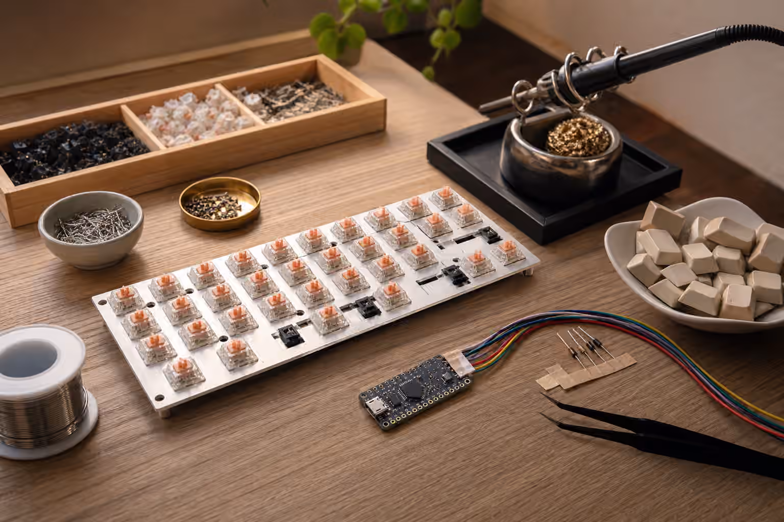
Hot-swap PCBs use sockets on the back of the board so switches can be pressed into place and removed later without desoldering. For many people, this is the best way to enter the hobby. It lets you try a heavier tactile switch, change to a quieter linear, or replace a faulty switch without rebuilding the whole board. It also makes careful experimentation possible. You can read the Complete Switch Guide , choose a sensible starting point, and still leave room for your taste to change.
The trade-off is that hot-swap sockets are fixed to specific switch positions. A solder PCB can often support multiple layout options because it has several possible switch holes for the same general area. A hot-swap PCB usually commits to one position because the socket occupies space on the underside. Some hot-swap PCBs do support a few alternatives, but they are less flexible than the most versatile solder designs. If you want a standard ANSI 65 percent or 75 percent board, that limitation may not matter. If you care about split spacebars, ISO, stepped Caps Lock, Tsangan bottom rows, or unusual right Shift options, read the PCB support carefully before buying.
Hot-swap also changes how you handle the board. Switch pins need to enter the socket cleanly. If a pin bends under the switch, the key may not work, and pushing harder can damage the socket. The right habit is slow pressure, straight alignment, and immediate inspection when something resists. A bent switch pin is a small problem before installation and a frustrating problem after the plate hides the view.
Sockets can fail, though most last a long time when treated well. The common failure is a socket lifting from the PCB after repeated rough swaps or after a switch was forced in with a bent pin. Repair can be possible, but it becomes soldering work. That is the quiet irony of hot-swap: it reduces the need for soldering, but it does not remove electronics from the keyboard forever.
Solder PCBs still have a place
Soldered keyboards feel less convenient because switch changes require desoldering, but solder PCBs remain common for good reasons. They can support more layout options, they remove the extra socket as a possible failure point, and they work well in designs where the maker wants the cleanest possible underside or a very specific internal structure. Some enthusiast boards use solder PCBs because the layout flexibility matters more than easy switch swapping.
The practical question is not which system is better. It is how much you expect to change. If you are building your first board and still learning switch preference, hot-swap is the calmer choice. If you already know your layout, your switch weight, and your tolerance for maintenance, solder can be perfectly reasonable. A solder PCB also makes sense for a board you intend to keep stable for years, especially if you enjoy the build process and are comfortable repairing it later.
There is also a middle path. Mill-Max sockets can be soldered into some compatible solder PCBs, turning them into a hot-swap-like board. That approach is useful when a board only ships with a solder PCB but you still want switch flexibility. It is not a shortcut for beginners, because installing the sockets neatly requires patience and good soldering technique. Treat it as a specialty option, not a default plan.
Switch footprints and pin compatibility
Most modern custom keyboards are built around MX-style switches, but even there the footprint details matter. A common MX switch has two metal pins that complete the electrical contact. Many also have two extra plastic legs that help align the switch in the PCB. Those extra legs are why people describe some switches as five-pin and others as three-pin. Five-pin switches fit a PCB that has the extra holes. Three-pin switches fit almost anywhere MX-style switches are supported. If a five-pin switch needs to go into a three-pin PCB, the plastic legs can often be clipped, but that is a one-way modification to the switch housing.
The plate changes the importance of those legs. In a plate-mounted build, the plate holds switches squarely, so three-pin switches are usually stable. In a plateless or half-plate build, the PCB does more alignment work, and five-pin switches become more valuable. That is one reason the PCB conversation connects naturally to Keyboard Mounting Styles and Plate Materials . The plate, mount, and PCB are not separate decisions when the build relies on them for structure.
North-facing and south-facing switch orientation is another compatibility detail that shows up as a lighting feature but affects keycap feel. On many MX-style PCBs, the LED position determines which way the switch is oriented. North-facing LEDs sit toward the top of the switch from the typist’s perspective. They can make RGB shine through legends more directly, which is why many mass-market boards use them. South-facing LEDs sit toward the typist and are common in enthusiast boards because they tend to avoid interference with Cherry-profile keycaps on certain rows.
Interference is not guaranteed on every combination, and many keycap profiles avoid it entirely. The point is that LED orientation should not be judged only by brightness. If you want Cherry-profile keycaps, south-facing support is often the safer choice. If you care more about shine-through legends, a north-facing board may make sense. Once again, the PCB is deciding something that seems like a keycap decision.
Layout support is a compatibility chain
A PCB can advertise layout support, but the build only works when the rest of the parts support the same positions. Consider a 65 percent board with optional split Backspace and split right Shift. The PCB may have the electrical positions. The plate needs matching cutouts. The stabilizer positions need to line up. The keycap set needs the correct small keys. The firmware needs a keymap for the chosen arrangement. If any link is missing, the option becomes theoretical.
This is especially important with bottom rows. Standard layouts are easy because most keycap sets include the required modifier sizes. More unusual bottom rows may require 1.5u modifiers, 7u spacebars, or extra keys that only larger kits include. A PCB that supports a beautiful layout can still lead to an annoying build if your keycaps do not. Before committing to a nonstandard layout, check the Keycaps guide and confirm that the set you want includes the actual keys, not just the colors.
Stabilizers are part of the same chain. A PCB may support screw-in stabilizers, snap-in stabilizers, plate-mount stabilizers, or a mix depending on the board. Screw-in stabilizers are popular in customs because they are secure and predictable, but they need the correct PCB holes and enough clearance. Plate-mount stabilizers depend on the plate instead. If you are tuning large keys, the Complete Stabilizer Guide explains the feel and sound side, but the PCB decides what can be installed in the first place.
Daughterboards, USB ports, and flex cuts
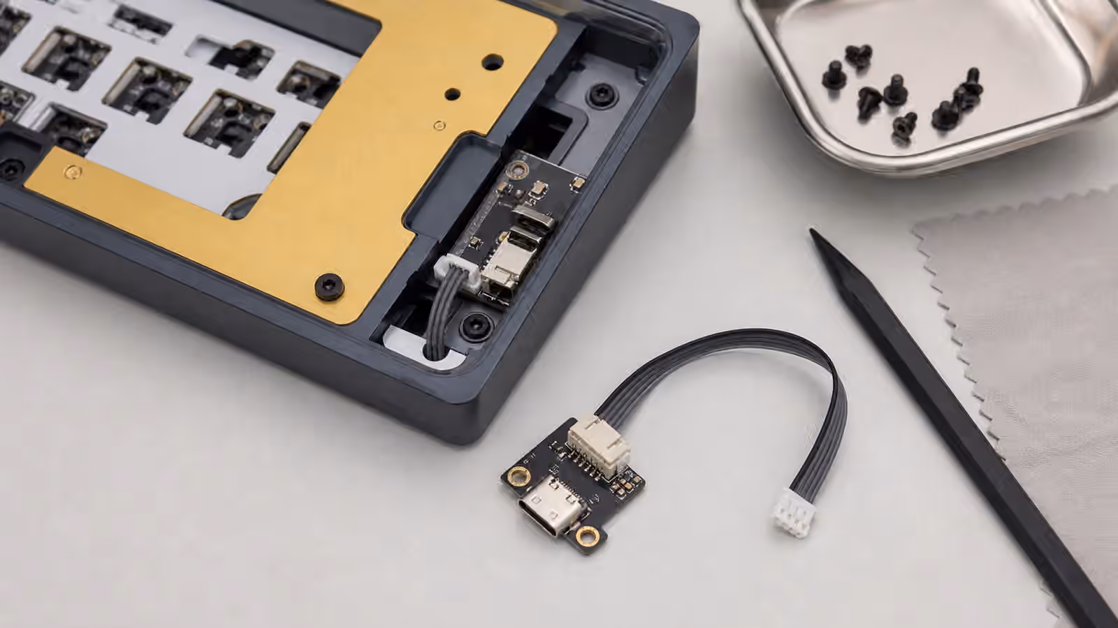
Some PCBs hold the USB port directly on the main board. Others use a small daughterboard connected by a cable. A daughterboard can reduce stress on the main PCB because the USB port is attached to a separate piece mounted near the case opening. It can also make case design cleaner, especially when the internal assembly moves on gaskets or other flexible mounting systems. The downside is one more cable and one more connector to seat correctly during assembly.
Flex cuts are slots in the PCB that allow parts of the board to bend more under typing force. They can make a build feel softer, especially when paired with a flexible plate and gasket mounting. They can also make the sound thinner or create uneven support if the rest of the design is not balanced. Flex cuts are not automatically comfortable, and a solid PCB is not automatically harsh. Think of them as one ingredient in the feel, not a badge of quality.
Wireless PCBs add another layer of decisions. They need space for a battery, a charging circuit, a power switch, and sometimes a different firmware workflow. They can be excellent for a clean desk, but they make case material and internal clearance more important. A heavy aluminum case can reduce wireless performance if the antenna placement is poor. A battery can conflict with foam or sound mods if the case was not designed with room for both. If wireless matters, buy a keyboard designed for wireless use rather than trying to improvise it into a wired-first kit.
Firmware support matters after assembly
The PCB and firmware are partners. A good PCB with awkward firmware can make simple changes irritating. A simple PCB with good VIA or QMK support can feel flexible because remapping is easy. Firmware decides how layers, macros, media keys, lighting, and special behaviors work after the physical layout is built. If you use compact layouts, that software layer matters because missing keys return through layers.
The QMK and VIA Firmware Guide covers programming in more detail, but the buying advice is straightforward. Prefer clear documentation, an available VIA definition or similar remapping tool, and a known reset method. A tiny reset button on the PCB is normal, but you should know where it is before the keyboard is sealed inside a case. If the board uses proprietary software, make sure it supports the basic remaps you actually need. Deep firmware power is less useful than reliable access to the few changes you will make every week.
A careful way to choose a PCB
Start from the layout you will use daily, not from the most flexible spec sheet. If you want a normal 75 percent board with easy switch changes, a hot-swap PCB with south-facing switches, screw-in stabilizer support, and VIA compatibility is a strong baseline. If you want a special bottom row, split Backspace, ISO, or split spacebars, confirm the entire compatibility chain before buying. If you want maximum layout freedom and do not mind permanence, a solder PCB may be the better tool.
Do not let the PCB become an afterthought. It is the part that turns a pile of attractive components into one working instrument. A good choice disappears under your fingers because everything fits, every key registers, the stabilizers mount cleanly, the firmware behaves, and future maintenance is predictable. A poor choice announces itself through bent pins, missing layout support, keycap interference, awkward remaps, and repairs you did not plan to learn yet. Read the PCB page slowly, match it to the plate and keycaps, and the rest of the build becomes much easier to trust.