A handwired keyboard replaces the manufactured PCB with deliberate wire work. The switches still sit in a plate or case, the keycaps still determine the touch surface, and firmware still turns presses into characters. What changes is the electrical path between each switch and the controller. Instead of traces hidden inside fiberglass, rows and columns are built by hand with wire, diodes, solder joints, and patience.
That makes handwiring both freeing and unforgiving. It can rescue an unusual layout that has no commercial PCB. It can turn a one-off case, a vintage shell, or an experimental ergonomic design into a working keyboard. It can also expose every weak assumption in the build. A commercial PCB gives you a clean map. A handwired board asks you to draw the map, build it, test it, and repair it when one row refuses to behave.
If you are building a conventional kit, read Building Your First Custom Keyboard and Keyboard PCBs and Hot-Swap Sockets first. Handwiring is not the calmer first path for most people. It makes sense when the layout, case, repair goal, or learning goal is strong enough to justify the extra work.
Why handwire at all
The best reason to handwire is layout freedom. A custom split, a strange macro pad, a vintage conversion, a sculpted case, or a keyboard with a nonstandard thumb cluster may not have a PCB waiting for it. Handwiring lets the physical design lead. If the plate holds switches securely and there is room for wiring and a controller, the project can become a keyboard.
The second reason is repair and preservation. Some older boards have damaged PCBs or controller systems that are difficult to replace. A careful handwire can keep the case, switches, and key feel alive while giving the board modern USB firmware. This is not always historically pure, and collectors may prefer reversible work, but for a daily-use board it can be the difference between display object and working tool.
The third reason is education. Handwiring teaches the keyboard matrix in a way diagrams alone do not. You learn why rows and columns exist, why diodes prevent ghosting, why firmware needs pin assignments, and why testing every small section matters. After one good handwire, commercial PCBs become easier to understand because the hidden structure is no longer abstract.
The matrix in plain language
A keyboard matrix is a grid of electrical paths. One set of wires is treated as rows, another as columns. Each switch connects one row to one column when pressed. The controller scans those paths quickly and asks which row-column intersections are closed. That is how a modest number of controller pins can read many keys.
Without a matrix, each switch would need its own direct wire to the controller. That can work for a tiny macro pad, but it becomes wasteful quickly. A five-by-fifteen matrix can read seventy-five switch positions with twenty controller pins, before accounting for special features. The matrix is what makes a keyboard practical without a huge controller.
Diodes are the small directional components that make the matrix trustworthy when several keys are pressed at once. They let current flow in one direction through each switch position and block paths that would otherwise create phantom keypresses. If you have read the Keyboard Rollover, Polling Rate, and Latency guide, this is one of the physical reasons rollover depends on design, not only firmware. A handwired matrix with proper diodes can handle normal multi-key input much more predictably than a bare switch grid.
Planning before solder touches metal
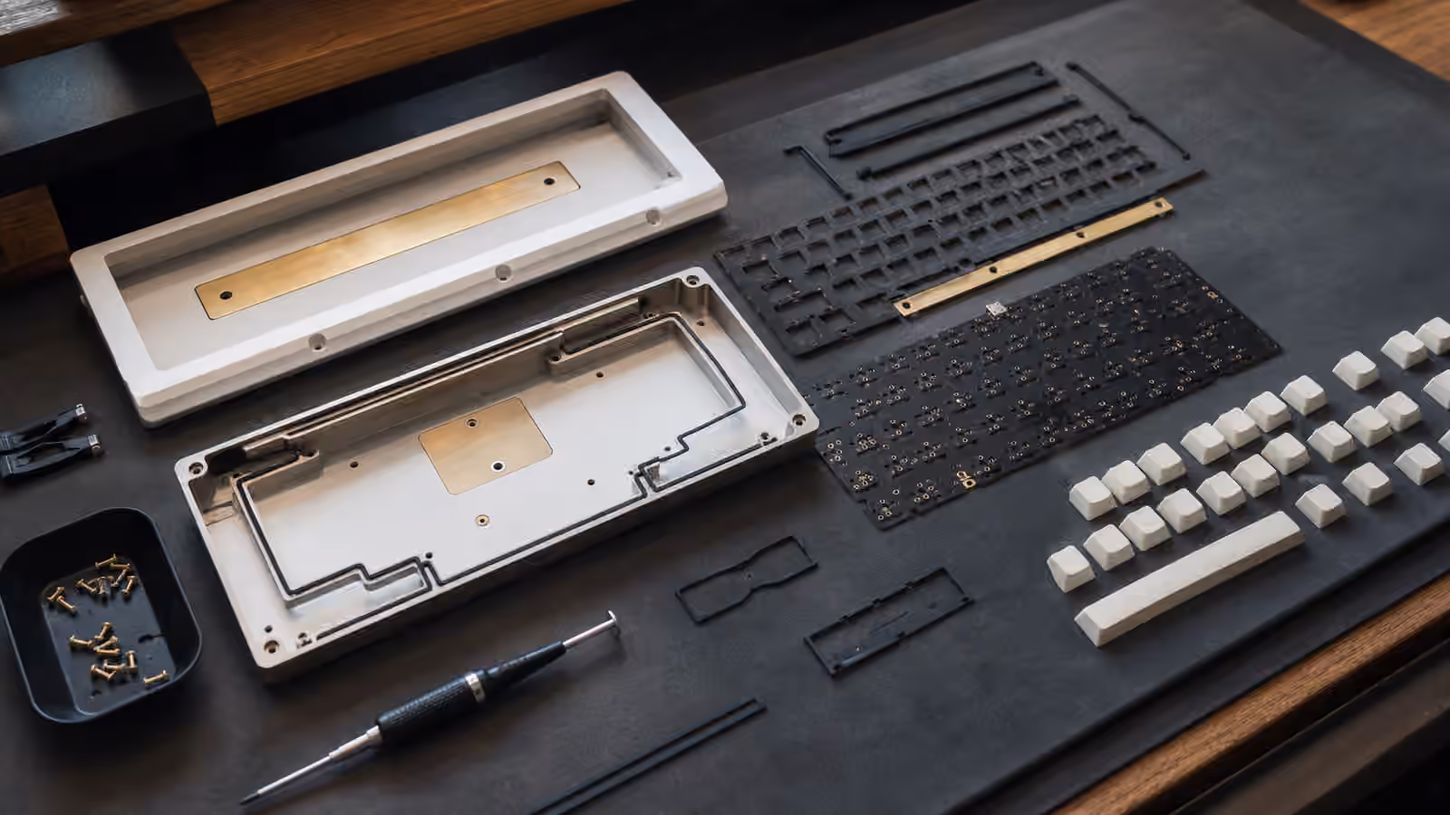
The easiest handwired mistake is beginning with the switches already in front of you and no complete plan. Before soldering, decide the layout, matrix size, diode direction, controller location, USB port access, reset access, mounting method, strain relief, and firmware target. A drawing is not optional. It does not need to be beautiful, but it needs to be clear enough that you can find row three and column seven a week later.
Start from the physical plate. Label the switch positions in a way that matches how firmware will see them. Then group the positions into rows and columns that route cleanly. In a rectangular keyboard, this may be straightforward. In a split or thumb-heavy layout, the cleanest electrical rows may not match visual rows. That is fine as long as the firmware map is honest. The computer does not care whether your thumb key is visually below the home row. It cares which controller pins and matrix coordinate represent it.
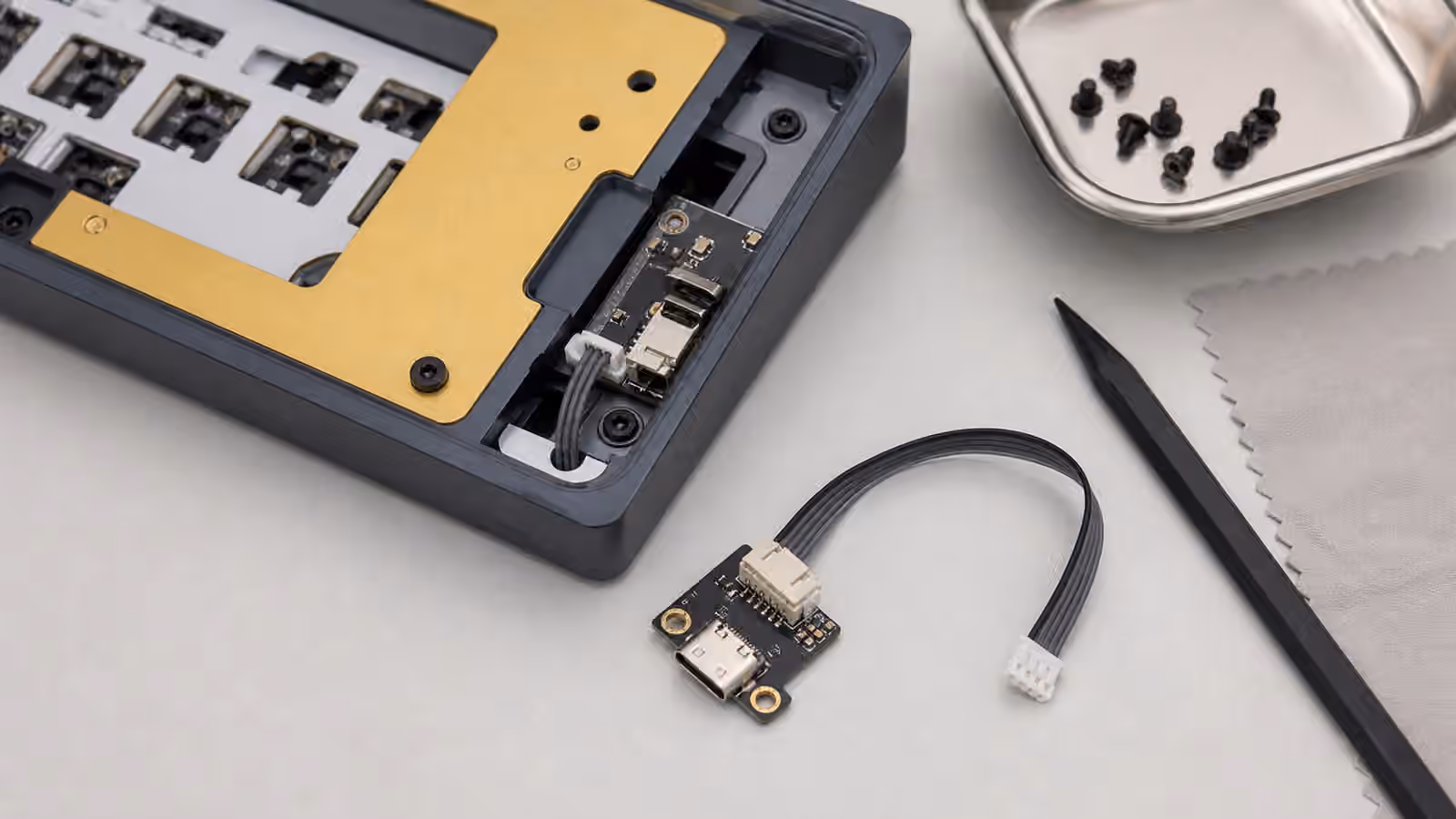
Controller placement deserves more thought than it gets. A microcontroller needs room, protection, access to USB, and enough pins. If the case is shallow, the controller may collide with the bottom. If the port opening is tight, a cable may not seat. If the reset button is buried, firmware flashing becomes annoying. The Keyboard Cables, USB Ports, and Desk Connectivity guide is useful here because a handwired board still lives or dies by a simple reliable USB connection.
Building clean rows and columns
Clean wiring is not about making the inside photogenic. It is about making faults visible. If every wire crosses every other wire at random, a single failed joint becomes a detective story. If rows and columns have a consistent route, you can follow the circuit with your eyes and a meter. That saves more time than any clever shortcut.
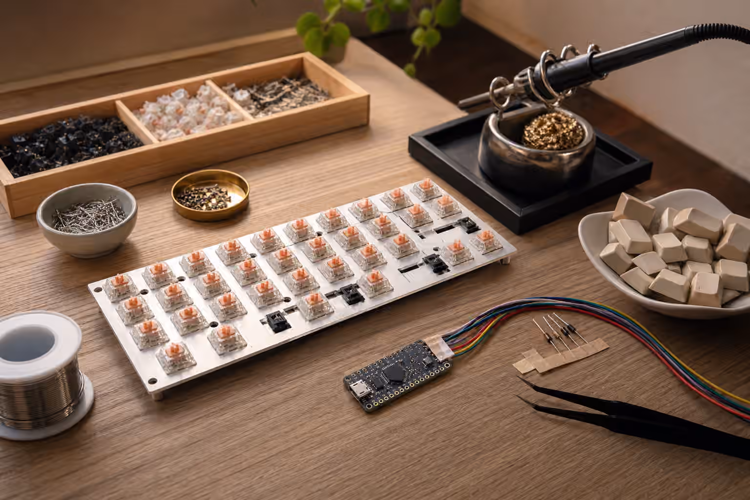
Many builders use bare bus wire for one side of the matrix and insulated wire for the other. Others use only insulated wire. The right choice depends on space, comfort, and the risk of accidental contact. Bare wire can be neat and efficient, but it punishes careless routing. Insulated wire is more forgiving but can become bulky in a tight case. Either way, every joint should be mechanically calm before solder flows. Solder is an electrical bond, not a clamp for parts under spring tension.
Diode orientation must be consistent. The firmware can usually be configured for row-to-column or column-to-row scanning, but the physical diodes need to agree with the plan. If one diode is reversed, that key may not register. If a whole row seems wrong, the issue may be a shared connection or a mistaken pin assignment. Mark the orientation in your drawing and check it before trimming leads.
Testing as a build habit
Handwired boards reward incremental testing. After soldering one row or a small cluster, use a multimeter to check continuity and shorts. After enough of the matrix exists, flash a simple firmware and test keys before the case is closed. Waiting until the entire board is assembled turns every possible fault into one large pile.
The test process should be boring. Press each switch, confirm the expected coordinate, and note anything odd. A key that works only when pressed hard may have a weak joint or a switch pin that was overheated. A whole column that fails may be a controller pin, firmware pin assignment, or broken shared wire. A key that triggers another key may reveal a short or a matrix coordinate mismatch. The Keyboard Troubleshooting guide covers symptoms at the user level, but a handwire lets you inspect the cause directly.
Firmware should begin simple. Make the matrix work before adding layers, home-row mods, tap dances, encoders, displays, or lighting. A working plain keyboard is a stable platform. A complicated broken keyboard gives you too many places to look. Once every physical key is trustworthy, the richer firmware layer can be added with less guesswork.
Structural details matter
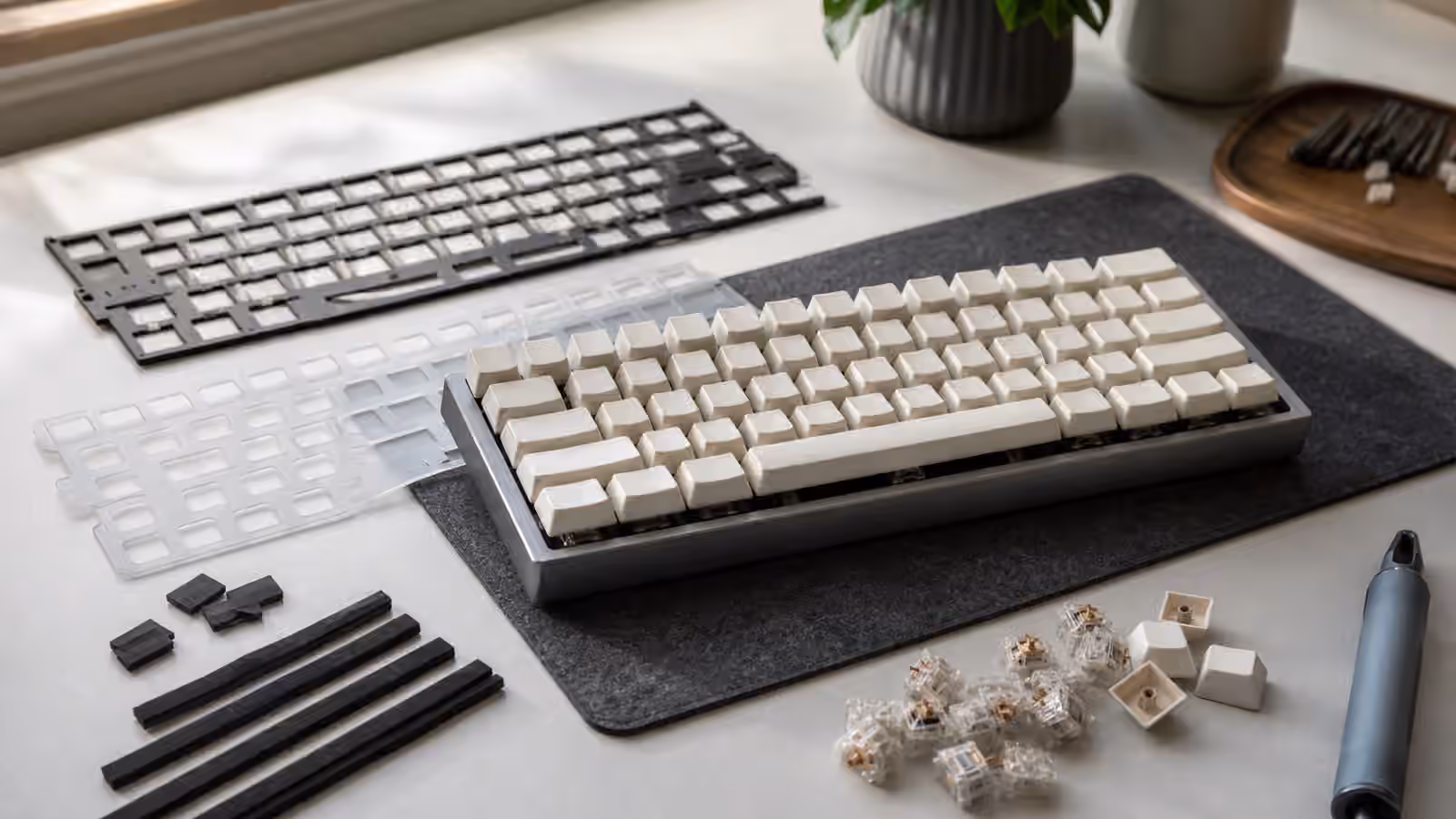
A handwired board needs physical support. The plate must hold switches firmly enough that normal typing does not flex solder joints. The controller should be mounted so the USB cable does not pull against tiny pins. Wires should not scrape against sharp case edges. If the keyboard will travel, the internal assembly needs more strain relief than a desk-only experiment.
This is one reason handwired projects pair naturally with thoughtful case and plate choices. The Keyboard Mounting Styles and Plate Materials guide explains how the plate carries typing force. In a handwired board, that force also protects the wiring. A loose plate or thin case can turn each keypress into movement at the solder joints. Over time, that movement becomes intermittent failure.
Leave service access when possible. If the controller is glued under a plate with no way to reach it, a simple repair becomes destructive. If every wire is pulled tight, lifting the assembly for inspection can break another joint. A little slack and a few deliberate tie-down points make the board easier to live with. The inside does not need to be overbuilt, but it should look like someone expected to repair it someday.
Where handwiring fits in the hobby
Handwiring is not a replacement for PCBs. For standard layouts, a good PCB is cleaner, repeatable, and easier to build. Hot-swap sockets make switch changes simple. Solder PCBs support many layouts without exposing a nest of wire. If a commercial PCB matches your case and layout, it is usually the practical choice.
Handwiring is for the places where practicality and curiosity overlap. It is slower, but it lets you build what does not exist. It teaches the matrix, makes firmware feel concrete, and turns a keyboard from a parts assembly into a small electrical project. The result can be durable and elegant if it is planned carefully. It can also be fragile if it is treated like a weekend shortcut.
Approach it with respect for the boring steps. Draw the matrix. Choose a controller with enough pins. Keep the wiring readable. Test in stages. Protect the USB connection. Build a simple firmware before the fancy one. A handwired keyboard does not need to be perfect inside, but it should be understandable. When you can open the case months later and still follow the rows, columns, diodes, and controller pins, the build has done more than work. It has become maintainable.